Flue Gas Desulfurization
Design, construction and commissioning of tailor-made systems and impartial enhancement of current facilities
 Ravebo recently celebrated a significant achievement by successfully completing its fiftieth FGD project. Throughout the years, numerous custom installations have been created, built in-house, and put into operation. Moreover, various existing installations for waste incineration plants have been enhanced and updated to meet current environmental standards. Ravebo has a rich history in spray nozzle technology and liquid-gas separation (droplet separation systems). These techniques have been advanced and implemented rapidly in recent years to ensure that FGD installations comply with the latest environmental regulations. This innovative approach has allowed for significant cost savings and minimal downtime, as the installations could be upgraded during routine maintenance shutdowns.
Given the accomplishments thus far, Ravebo is committed to further developing and refining these technologies in the future, playing a crucial role in reducing waste landfills and promoting environmentally responsible waste incineration. For your reference, we have outlined below a simplified explanation of how a typical FGD installation is constructed and operates.
Flue gas cleaning installations are employed to diminish the high levels of detrimental substances present in the flue gases generated from the combustion of household and industrial waste. These harmful substances, which pose a threat to the environment, must be reduced to comply with legal regulations.
- Fly ash
- Halogens
- SOx
- Dioxins/ Furans
- PCB’s
Following the cooling of the flue gas after the boiler, it is brought down to the necessary operating temperature for the electrostatic precipitator (ESP). The ESP effectively separates most of the fly ash contained in the flue gas. Subsequently, in two wet scrubbers, residues such as fly ash, halogens, heavy metals, and SO2 are removed. The washing liquid used is circulating water, which is continuously refreshed with fresh make up water. The negative pressure in the boiler is maintained by the suction draught fan through a negative pressure control mechanism. Dioxins/furans, PCBs, and other harmful substances are then adsorbed onto the activated carbon surface in the activated carbon filter. Finally, NOx is eliminated from the flue gas by reacting with injected ammonia in the presence of a catalytic converter to produce nitrogen and water. The flue gas, now meeting the emission limit values, exits the flue gas cleaning system through the chimney.
 The 2-stage wet cleaning consists of two gas scrubbers placed in series, namely acid scrubber and alkaline scrubber
Function
- Cooling of the flue gases.
- Absorption of the gaseous pollutants present in the flue gas.
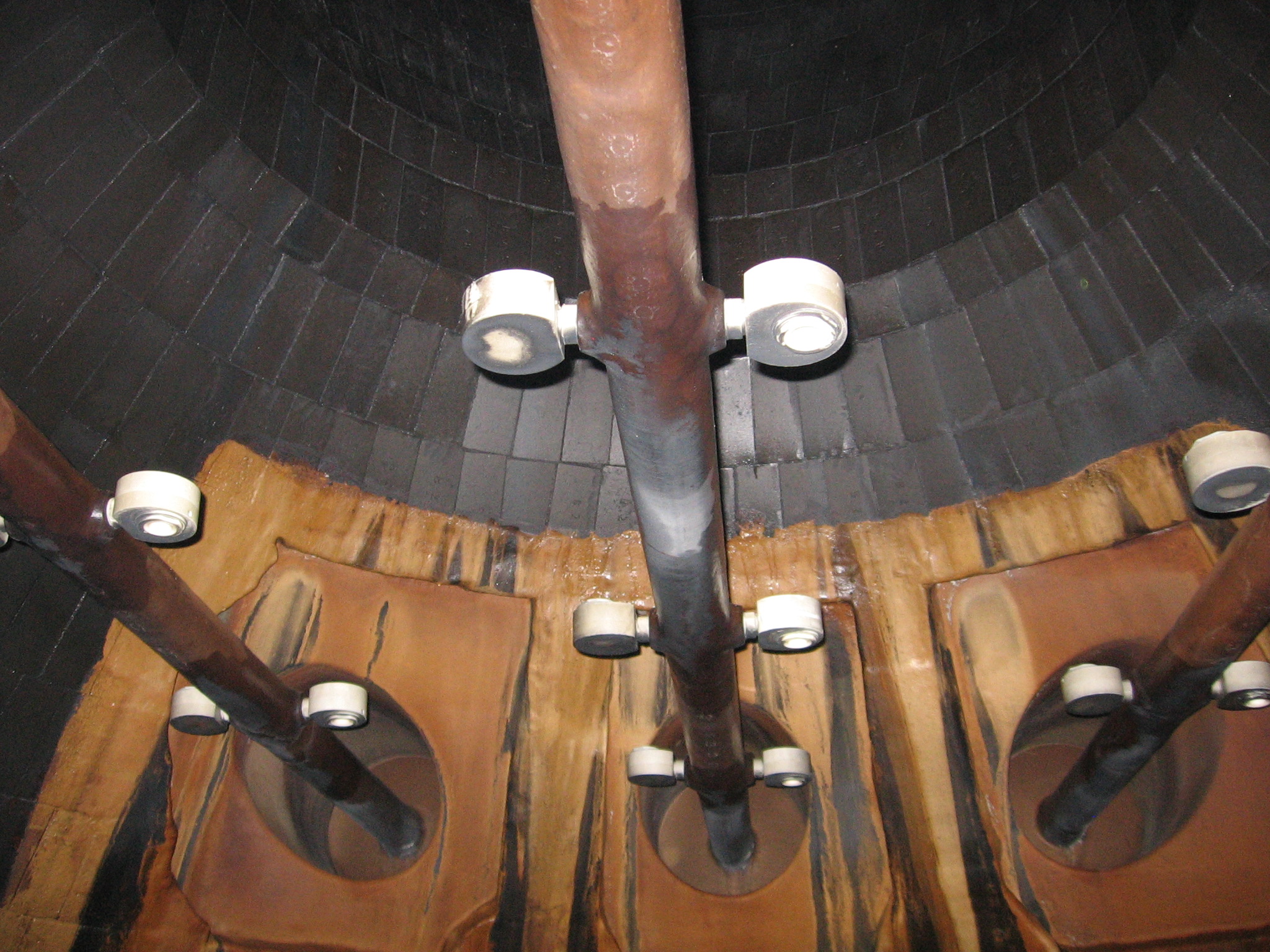
The gaseous pollutants are absorbed by water in the two gas scrubbers. Water is sprayed into the scrubbers through spray nozzles, creating a spray pattern with small water droplets that allow for intense contact between water and flue gas. The efficiency of separation of harmful substances increases with better contact between water and flue gas. The two scrubbers are uniquely designed to operate at different pH values and with distinct neutralizing agents, ensuring optimal conditions for the quantitative separation of various gaseous pollutants or pollutant groups. Typically, the process water in the acid scrubber maintains a pH value of around 1.5, while the process water in the SO2 scrubber usually has a pH value slightly above 6. A droplet separator is positioned between the acid scrubber and the SO2 scrubber, as well as after the SO2 scrubber, to eliminate droplets from the gas stream.
Acid scrubber
- Adsorption of sulphur trioxide (SO3), hydrochloric acid (HCl), hydrogen bromide (HBr), hydrogen iodide (HI), hydrogen fluoride (HF), mercury (Hg), fly ash residues and other heavy metals.
- Cooling of the flue gases by means of quenching with washing liquid.
Following the removal of dust in an electro filter prior to separation, the flue gas is directed towards the acid scrubber. Within the initial section of the scrubber, known as the quench, spray nozzles are typically utilized for regular or emergency spraying purposes. Process water is circulated from a buffer, ensuring that any water lost through evaporation during the cooling of the flue gases, as well as through draining, is consistently replaced. During the quenching process, the flue gases are cooled from approximately 180°C to temperatures below 70°C.
To prevent the formation of foam in the scrubber, an anti-foaming agent is frequently introduced. Within the quench, the process water, which is circulated by pumps, is dispersed and cooled. As the flue gas comes into close contact with the process water atomized by the spray nozzles, an initial separation of the harmful substances occurs in the quench. The washing water, which cannot be absorbed by the flue gas (already saturated with water vapor), trickles down the quench wall and returns to the reservoir integrated in the scrubber. Following the quench, the flue gas passes through the acid scrubber. This is the primary location where the removal of harmful gases such as HCl, HF, SO3, and Hg compounds occurs. The value in the process water basin is maintained at around pH 1.5 by the addition of milk of lime. In case the pH value decreases, liquid lime is added to restore the pH value to the desired level.
Residual dust, along with the heavy metals it carries, is removed in the process, which was not achieved by the electro filter. To prevent the release of SO2 (which reacts with liquid lime to form gypsum), the value of the process water must be maintained below pH 2. Periodic drainage is conducted to avoid an increase in the concentration of harmful substances and salts in the process water. The discharge from a scrubber is not constant, but rather depends on the boiler load, as it is the difference between operating water replenishment and evaporation. The desired blowdown amount is approximately 15% of the water consumption. In typical FGD installations, evaporation in the scrubber accounts for about 85% of the water consumption.
Intermediate droplet separator
 The droplets are separated from the acid scrubber based on the principle of mass inertia, effectively stopping any harmful substances from being transferred from the acid scrubber to the SO2 scrubber. As the flue gas changes direction, the water droplets are expelled due to centrifugal force and are collected on the walls. Consequently, the water is eventually sent back to the reservoir of the acid scrubber. In case the pressure difference across the droplet catcher becomes too high, it is automatically cleaned by nozzles every twenty minutes.
SO2 scrubber
- Removal of sulphur dioxide SO2
- Removal of hydrogen fluoride HF
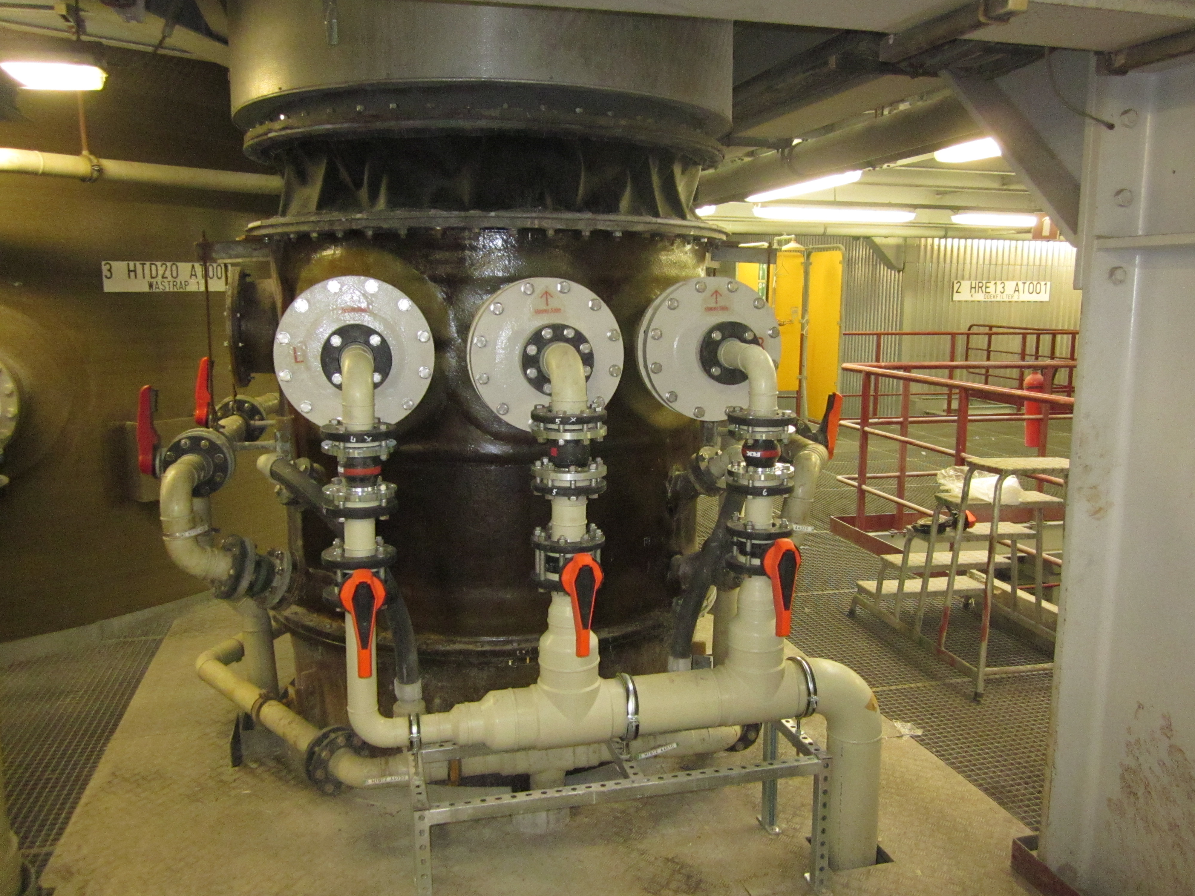
The second phase of the wet cleaning process involves the utilization of an SO2 scrubber equipped with circulation pumps. This particular scrubber is designed in a counterflow configuration. The scrubber is structured as a cylindrical column featuring multiple levels of spray nozzles and an integrated buffer. Through the operation of the pumps, the process water is brought into counterflow contact with the flue gases. To prevent an escalation in the concentration of harmful substances, clean water is continuously added into the process water. The level within the buffer is maintained at a constant level by discharging the water to a wastewater treatment and replenishing it with fresh water. Caustic soda serves as a neutralizing agent in this process. In the event of a decrease in pH value, caustic soda is administered until the value is restored to the desired level of pH >6. Furthermore, the introduction of caustic soda enhances the removal of SO2, as the two substances undergo an immediate reaction upon contact.
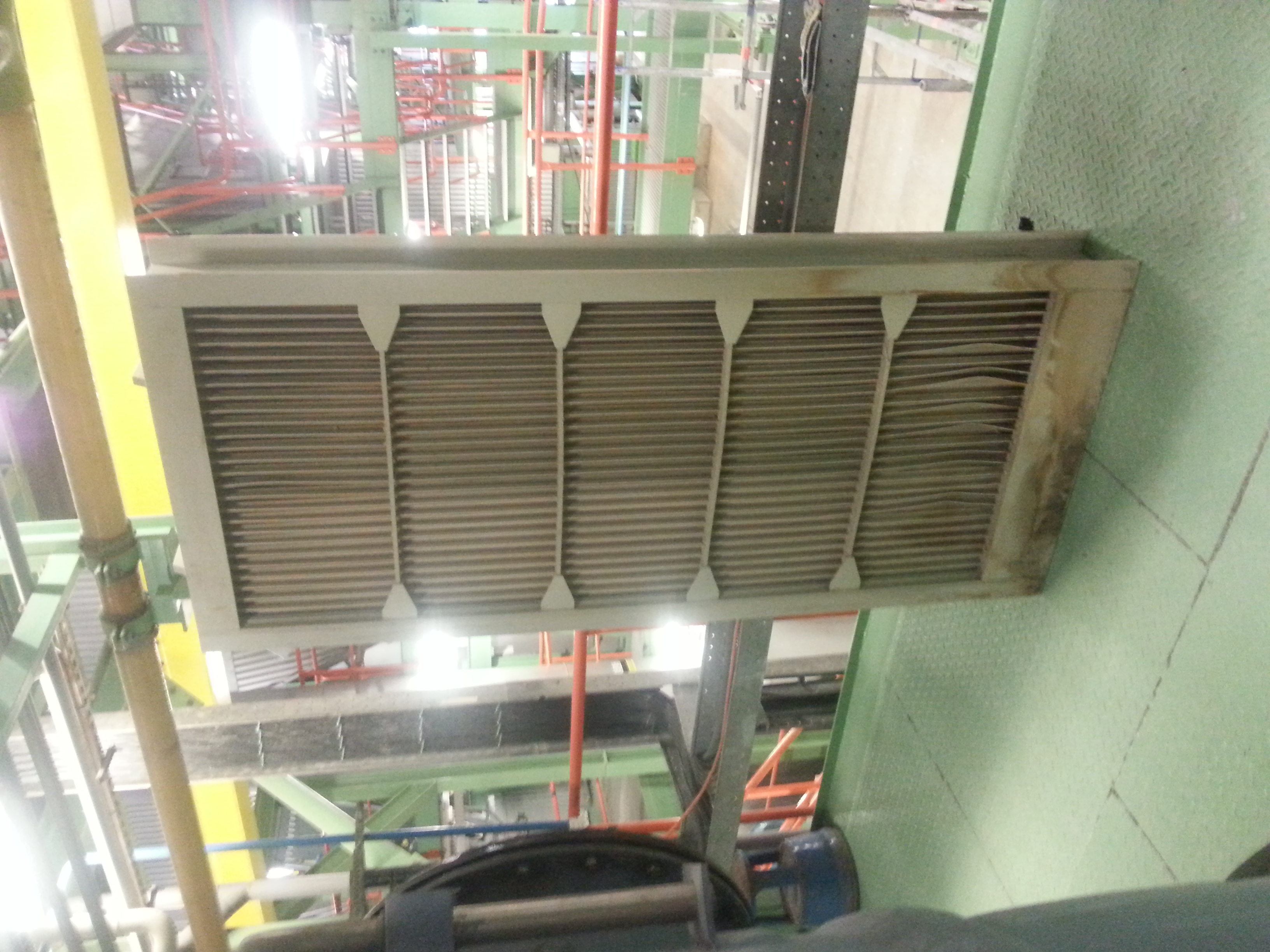
Droplet separator
Behind the SO2 scrubber, the flue gases are directed into a high-capacity droplet separator, where water droplets in the flue gas are removed using the principle of mass inertia. The droplets are separated from the profile walls due to the favorable shape of the profiles. The liquid that comes into contact with the profile wall flows down the slats vertically. A suitable flushing system is in place to prevent blockages in the droplet separators. The droplet separator is equipped with spray nozzles for intermittent cleaning, where operating water is admitted to the nozzles to clean the droplet separator. The rinse water is then returned to the SO2 scrubber.